2016年2月27日星期六

Week 4 of Group Project


Last week, we tested the control circuit but failed to use the IR emitter and receiver to generate the signal. However we found some solution to this problem.


This week, we firstly finished the work on the program for LPC1768. In this program, we mainly use digital signal as the input signal because for LCP1768, the digital high voltage is the voltage that more than 2.0V, and the digital low voltage is below 0.8V. It is easy to generate the signal. The pin usage of inputs and outputs are as follow:


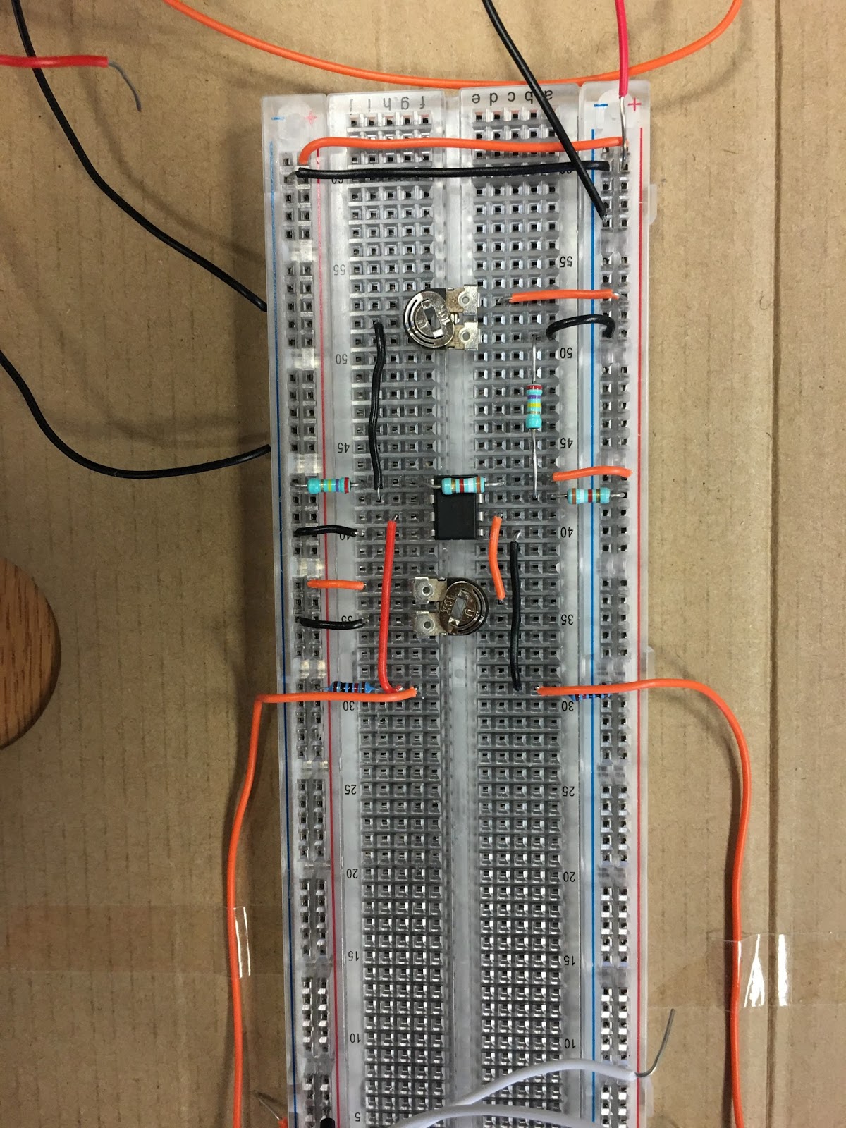
The basic principle of this program is to get the digital input from the circuit to decide wether there are someone come in or not. There are two pair of sensor in the circuit to test these condition. If no one pass through the door, both two pairs will give digital low to the board and the program will take no action.

If someone come into the room, the first sensor pair will get the pause and give out a digital high, the second sensor pair will give out a digital low, therefore the program can make a proper change to variables that hold the corresponding data.

If someone get out of the room, the second sensor pair will get the pause and give out a digital high, the first sensor pair will give out a digital low, therefore the program can make a proper change to variables that hold the corresponding data. 


The program will count the time since the while loop was started and when it reach a significant time, the loop will break, the data will write into a file that saved at an USB and finally, the program was close.


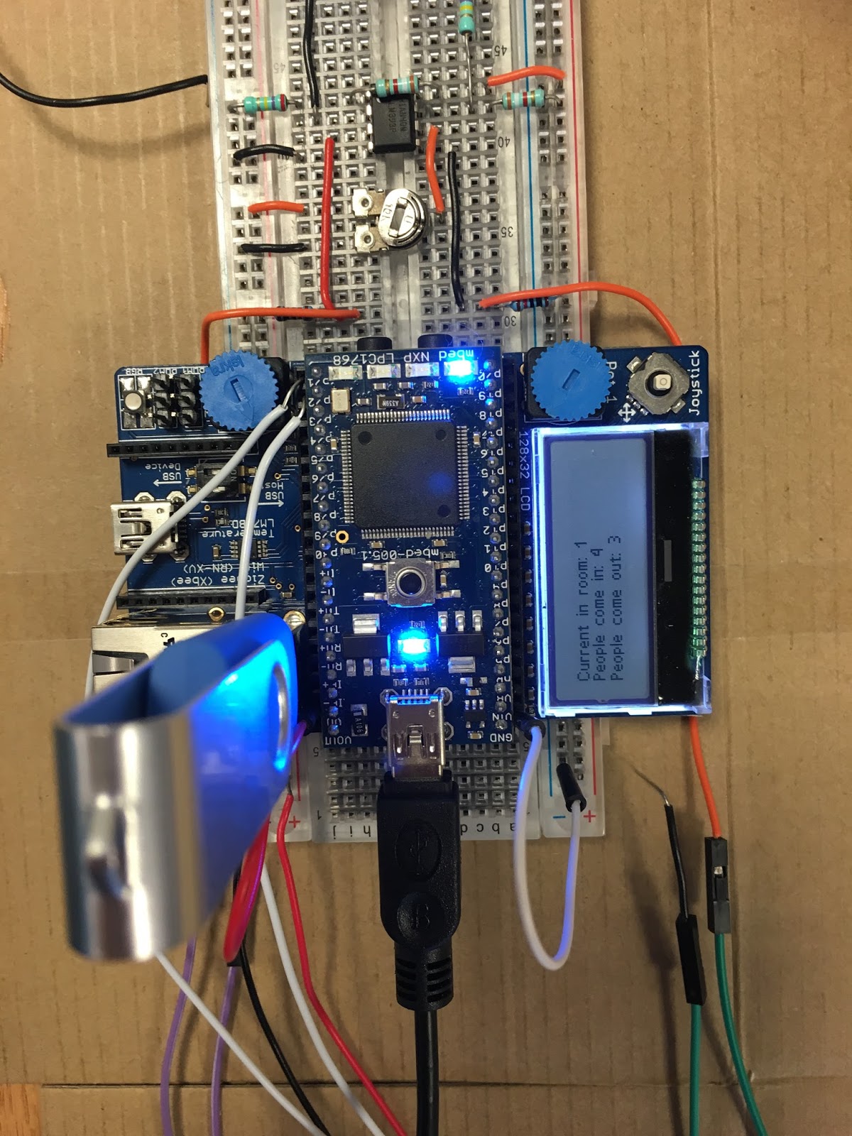
Below is the operation state of the microprocessor


This week, we also tried some ways to solve the distance problem of the IR sensor pair but no progress was made. Therefore we start to consider the design using laser diodes and photoresistors. Using this kind of sensor pair, the distance problem was solved. We will make more efforts on laser diodes and photoresistors but will not give up to use the IR emitters and receivers.

Following is a video link of the laser detector system we built during our testing.

https://youtu.be/YwuHotEfJQ8

2016年2月21日星期日

Week 3 of Group Project

The Group Project: Bidirectional Visitor Counter using ARM Microcontroller


Last week, we drew the circuit simulation layout which is based on a voltage comparator (LM393). This week, we began to connect the circuit on the breadboard. As can be seen on the following figure, we added a LED in the circuit. When the LED turns on, it indicates there is a high output and one person has entered the door. At first, we did not connect the IR transmitter and receiver in the circuit. In consequence, we adjusted the magnitude of resistor ourselves to achieve the high and low output voltage. We also loaded the program in the ARM, so that the screen could show the current number of the people on the LCD when the output voltage is high. 


Then we started to connect the IR transmitter and receiver circuit. The simulation layout looks simple, however, we failed in this part. The IR receiver was not capable of receiving the signal transmitted by the IR transmitter. We tried many times but the result was the same. The reason we finally figured out was that the signal power was low. There are two methods to solve this problem. The first one is to change a higher power transmitter. Another way is to add an amplifier in the circuit. We chose the second solution and began to design the amplifying circuit this week.


2016年2月19日星期五

Week 2 of Group Project

The Group Project: Bidirectional Visitor Counter using ARM Microcontroller

In the second lab day, we focused on the simulation of the IR emitter and receiver. First of all, both emitter and receiver are analog components so that we have to build analog-to-digital circuit using a voltage comparator (LM393).
      
There are two input voltages V5 and V6, and V7 is the output voltage. The function is that we V5 > V6 there will be a high output that can be distinguished as 1 by the microprocessor. Whilst when V5 < V6 the output will be low as 0. At the same time, terminal 8 and 4 are connected to the vcc and ground separately. 

The simulation is below

Here we it can be seen that when there is no received signal the transistor operate as open circuit so that input voltage v2 is smaller that v1, so the output is high which informs the microprocessor that there is someone coming in or out.


When the emitter works, the photo transistor will receive IR signal and acts as short circuit so that the v2 can be higher that v1, so the output is Low. This is the case that there is no one crossing the system.

However, we still have some problems in the circuit design one of which is that the actual diode and transistor can not perform ideally so that we have to control the input current and voltage to make both emitter and receiver work stably. 

Below is the real connection.


Week 1 of Group Project

The Group Project: Bidirectional Visitor Counter using ARM Microcontroller

The objective of our group project is to build a counter circuit using IR emitter and receiver. There are basically 3 modules of the assignment, and the first one is the sensor, the second one is the controlling circuit while the last part is the ARM microprocessor and LCD display. 

For the sensor(s),  the infrared (IR) sensors are considered because they are not too much expensive. Compared with other sensors such as the weight sensors, distance sensors and laser sensors, IR sensors do not need complex conditions to promise them to work stably.


Here we have a test of the IR sensor. The figure below shows an IR switch sensor which emits signals continuously. When there is an object obstructing the receiving signal, the LED would light. This indicates an passing through of human.


At the same time, we have also scoped the outline of the completed circuit. The connection of IR sensors and microprocessor is the most significant part that there should be a controlling circuit. We are trying to built our own circuit base on the circuit with the ARM LPC microprocessor provided by our tutor. However, to sketch the circuit, we have to use Intel 8051 instead of ARM due to limitations of sources in the simulation software. Below is the basic circuit.


Therefore, for the next week we will focus on the IR sensors and controlling circuit. In addition, we will also refer some references to handle some theoretical problems.