In the second lab day, we focused on the simulation of the IR emitter and receiver. First of all, both emitter and receiver are analog components so that we have to build analog-to-digital circuit using a voltage comparator (LM393).


There are two input voltages V5 and V6, and V7 is the output voltage. The function is that we V5 > V6 there will be a high output that can be distinguished as 1 by the microprocessor. Whilst when V5 < V6 the output will be low as 0. At the same time, terminal 8 and 4 are connected to the vcc and ground separately.
The simulation is below

Here we it can be seen that when there is no received signal the transistor operate as open circuit so that input voltage v2 is smaller that v1, so the output is high which informs the microprocessor that there is someone coming in or out.

When the emitter works, the photo transistor will receive IR signal and acts as short circuit so that the v2 can be higher that v1, so the output is Low. This is the case that there is no one crossing the system.
However, we still have some problems in the circuit design one of which is that the actual diode and transistor can not perform ideally so that we have to control the input current and voltage to make both emitter and receiver work stably.
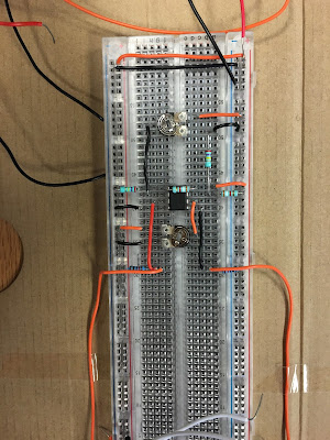
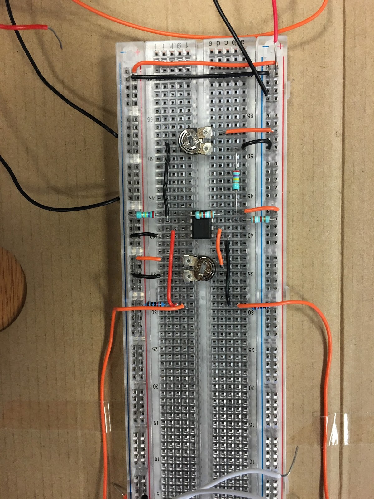
Below is the real connection.
没有评论:
发表评论